[Jarrod] sent us a link to this home-built laser projector after seeing a different projector that we featured yesterday. This system is fundamentally different. [ChaN], who finished the project several years ago, didn’t use a loudspeaker to move the mirrors, but instead build his own closed-loop Galvanometers. Two of these are controlled by an ATmega64 to produce incredibly clean and accurate vector images. It’s not just the images that are impressive, his hardware is laid-out with skill and forethought that make hiding it in a case a sacrilege.
[Rich] over at NothingLabs has put together a really cool laser light show that you really must see in an effort to win a laser cutter from Instructables.
His walkthrough discusses the mechanics of laser light shows – specifically how galvanometers are typically used to precisely aim mirrors in order to draw images and write text. Commercial galvanometers tend to be pretty expensive, so he opted to build his own, using relatively cheap and easy to find parts.
The galvanometers were constructed using a pair of old speaker woofers, a few Lego bricks, and some acrylic mirror squares. The mirrors were mounted on the speakers, which were then wired to an Arduino. He removed the batteries from a cheap red laser pointer and permanently wired it to the Arduino, which it now uses as a pulsed power source. Once he had everything built, he positioned the laser using a fog machine for guidance.
As you can see in the video below, the laser show is quite impressive. His homemade galvos provide a somewhat rough quality to the final projected image, and we like that a lot. It looks almost as if all of the text and images were hand drawn, which is a pretty cool effect.
Just as [Rich] mentions, we hope to see some cool hacks based off his work in the future.
If you are interested in some of our previous laser features, checktheseout.
He started by removing all of the electronics from the cabinet for further study in his lair. He examined the signal generator which when scoped seemed to be putting out some very nice sine waves as it should. From there he moved on to the galvos which tested way off of spec and turned out to be the offending elements.
A bit of searching around the interwebs and [Bill] figured out an upgrade plan for the older parts. But since he was at it, why not add some features at the same time? He rolled in a port so that just a bit of additional circuitry added later will allow shapes and logos to be drawn on the screen. One of his inspirations for this functionality came from another DIY laser projector project.
Take a look at the results of the repair process in the clip after the break.
I suppose I can take credit for introducing the super awesome [Fran Blanche] to Hackaday’s very own crotchety old man and Commodore refugee [Bil Herd]. I therefore take complete responsibility for [Fran] and [Bil]’s Dinosaur Den, the new YouTube series they’re working on.
The highlight of this week’s episode is a very vintage Rubicon mirror galvanometer. This was one of the first ways to accurately measure voltage, and works kind of like a normal panel meter on steroids. In your bone stock panel meter, a small coil moves a needle to display whatever you’re measuring. In a mirror galvanometer, a coil twists a wire that is connected to a mirror. By shining a light on this mirror and having the reflected beam bounce around several other mirrors, the angle of the mirror controlled by the coil is greatly exaggerated, making for a very, very accurate measurement. It’s so sensitive the output of a lemon battery is off the scale, all from a time earlier than the two dinosaurs showing this tech off. Neat stuff.
One last thing. Because [Bil] and [Fran] are far too proud to sink to the level of so many YouTube channels, here’s the requisite, “like comment and subscribe” pitch you won’t hear them say. Oh, [Bil] knows the audio is screwed up in places. Be sure to comment on that.
After two years of EE coursework, [Joshua Bateman] and [Adam Catley] were looking for a fun summer project. Instead of limping along with the resources they could put together themselves, they managed to get their school — Bristol University — to foot the bill!
Now Uni’s aren’t in the habit of just forking over funding for no reason, and we thing that’s why the two did such a great job of documenting their work. We’re used to seeing blogs devoted to one project, but this one has a vast portfolio of every piece of work that went into the build. Before any assembly started they drew out design diagrams to form the specification, laid out the circuit and the board artwork, and even worked out how the software would function in order to make sure the hardware met all their needs.
When the parts arrived the work of hand-populating the surface mount boards began. This is reflected in the fast-motion video they recorded including this clip which features a 176 pin LQFP. The driver board is a shield for a Raspberry Pi which drives the Galvanometers responsible for the X and Y movements of the mirror.
The video below shows off their success and the blog makes a great resource to point to when applying for work once a freshly minted diploma is in hand.
So you’re a boxer, and you’re weighing in just 80 micrograms too much for your usual weight class. How many eyelashes do you need to pluck out to get back in the ring? Or maybe you’re following the newest diet fad, “microcooking”, and a recipe calls for 750 micrograms of sugar, and you need to know how many grains that is. You need a microgram scale.
OK, we can’t really come up with a good reason to weigh an eyelash, except to say that you did. Anyway, not one but two separate YouTube videos show you how to build a microgram balance out of the mechanism in a panel meter. You know, the kind with the swinging pointer that they used to use before digital?
Panel meters are essentially an electromagnet on a spring in the field of a permanent magnet (a galvanometer). When no current flows through the electromagnet, the spring pulls the needle far left. As you push current through the electromagnet, it is attracted to the fixed permanent magnet, fighting the spring, and tugs the pointer over to the right. More current equals more pull.
The first link, from [Paul Grohe] of Texas Instruments, demonstrated the basic principle. Arrange the meter so that the arm falls into the path of an opto-interrupter, and then build a small circuit that passes more current through the meter’s electromagnet to pull the arm back up when the arm breaks the beam.
When the arm falls, because you’ve put an eyelash on it, it’ll break the beam which drives more current which pulls the arm back up. This will wobble back and forth until it settles with the arm just breaking the beam. Then you can read off the current required to hold it up, and that’ll be proportional to the weight.
The second link, from [Applied Science] goes into a lot more detail. [Ben Krasnow] reconstructs [Grohe]’s circuit and investigates the balance’s linearity (good) and stability (so-so), and demonstrates how to calibrate the scale with squares of paper. He also discovers that his plastic housing is pulling on the mechanism, because of static charge.
[Ben] is easily able to get around 10 microgram precision out of a couple of bucks in parts sitting on his desk. Plus, his hands-on approach to characterizing and debugging the setup really warms our heart.
(And the answers are: 80 micrograms is two eyelashes; ten grains of sugar weigh around 750 micrograms.)
Thanks to [Travis Swaim] for sending us the links.
Last year, [Alvaro] built a laser turret robot for the DEFCONBOTs competition. It worked pretty well, but this year, he decided to step it up a notch. Now instead of moving the entire robot laser array, he’s using galvanometers to move only the laser — he’s essentially built a mini laser projector.
A galvanometer is basically a very sensitive ammeter that moves — it can also be used as a very precise electro-mechanical actuator, for say, moving a tiny mirror. As you can imagine, you can actually build home-made galvanometers — but it’s really not that easy. Instead, [Alvaro] opted to order a few laser show controllers on eBay, and hack his way to a solution — we approve.
Wiring up the galvanometers and making some circuitry for them was the easy part. The tricky part is automating the system.
You see before when the laser was attached to the camera, it was pretty simple. The laser shoots where the camera shoots. Any simple image recognition software would work. But now that the two are independent, it’s not that simple. If you could mount everything precisely, you could use trig to calculate laser angles and the resulting locations, but the problem is… mounting everything precisely:
If I was a machining/CAD wizard, I could mount the laser, galvanometers, and camera precisely enough that I could use some math to calculate angles/depths and figure out where the laser is going.
As I mentioned previously though, I am no CAD wizard, and my mechanical skills are… lacking. With no mechanical solution to the problem, I had to start getting creative with software.
His software solution is pretty cool. It requires calibration by creating a grid of pre-defined points, but from there, the possibilities are pretty endless. Take a look.
And now some ping pong balls as targets.
And finally — a moving train.
Anyone remember that laser targeting mosquito system? Why aren’t those in production yet! Get on it [Alvaro]!
A ‘meter is one of the most important tools on any electronics bench. After you’ve exhausted your five senses trying to figure out what’s happening in a circuit, firing up the old ‘meter is usually the next step. Meters are largely digital nowadays, but their analog ancestors are still widely available. We have a chemist and inventor named [Edward Weston] to thank for the portability and ubiquity of DC measuring equipment.
After immigrating to the United States from England with the degree in medicine his parents wanted him to earn, [Edward Weston] asserted that he was more interested in chemistry. His career began in electroplating, where he soon realized that he needed a reliable, constant current source to do quality plating. This intense interest in power generation led him to develop a saturated cadmium cell, which is known as the Weston cell. Its chemistry produces a voltage stable enough to be used for meter calibration. The Weston cell is also good for making EMF determinations.
Within a few years, he co-founded the Weston Electrical Instrument Corporation. The company produced several types of meters along with transformers and transducers known for their portability and accuracy. In 1920, [Weston & Co.] created this 1920 educational film in cooperation with the United States Navy as part of a series on the principles of electricity.
The viewer is invited to consider the importance of measurement to civilization, most notably those fundamental measurements of length, mass, and time. [Weston] positions his electrical measuring instruments at this level, touting them as the international favorite. We get the full tour of a Weston meter, from the magnet treated for permanence to the specially designed pole pieces that correctly distribute lines of magnetic force. What education film about electromagnetism would be complete without an iron filings demonstration? This one definitely delivers.
Mirror galvanometers were originally developed in the 17th century to precisely measure very small changes in current. Unlike other instruments of the day, a mirror galvanometer could clearly show minute current variations by translating tiny movements of the mirror into large movements of the light reflected off of the mirror. Before clean electrical amplification became possible, this was the best means of measuring tiny differences in current. True mirror galvanometers are very sensitive instruments, but hobby servos can be used as a low-fidelity alternative, like with this project on Hackaday.io created by [robives].
Using a mirror galvanometer is by far the most common technique for laser projection shows – it’s really the only way to move the laser’s beam quickly enough to create the visual illusion of a solid line in real time. A mirror galvanometer works by using coils to attract magnets attached to the mirror, allowing the angle of the mirror to change when current is applied to the coils. This movement is extremely small, but is amplified by the distance to the projection surface, meaning the laser’s beam can move huge distances in an instance. If you’ve ever seen a laser show, it almost certainly used this technique. But driving galvos requires a beefy DAC, so we can’t blame [robives] for wanting to keep it digital.
[robives’s] project side-steps the need for galvanometers by using glow-in-the-dark vinyl and a UV laser. The result is a laser beam trail which lasts much longer, which means that solid lines are visible without the need for high-speed galvos. A build like this lets you experiment with laser projections without dealing with sensitive mirror galvos, and instead use components that you probably already have sitting on your workbench.
Motors are everywhere; DC motors, AC motors, steppers, and a host of others. In this article, I’m going to look beyond these common devices and search out more esoteric and unusual electronic actuators that might just find a place in one of your projects. In any case, their mechanisms are interesting in their own right! Join me after the break for a survey of piezo, magnetostrictive, magnetorheological, voice coils, galvonometers, and other devices. I’d love to hear about your favorite actuators and motors too, so please comment below!
Piezoelectric materials sometimes seem magic. Apply a voltage to a piezoelectric material and it will move, as simple as that. The catch of course is that it doesn’t move very much. The piezoelectric device you’re probably most familiar with is the humble buzzer. You’d usually drive these with less than 10 volts. While a buzzer will produce a clearly audible sound you can’t really see it flexing (as it does shown above).
To gauge the motion of a buzzer I recently attempted to drive one with a 150 volt piezo driver, this resulted in a total deflection of around 0.1mm. Not very much by normal standards!
The PiezoMotor LEGS actuator “walks” along a rod, pushing it as it goes.
For some applications however resolution is of primary interest rather than range of travel. It is here that piezo actuators really shine. The poster-boy application of piezo actuators is perhaps the scanning probe microscope. These often require sub-nanometer accuracy (less than 1000th of 1000th of 1 millimeter) in order to visualize individual atoms. Piezo stacks are ideal here (though hackers have also used cheap buzzers!).
Sometimes though you need high precision over a larger range of travel. There are a number of piezo configurations that allow this. Notably Inchworm, “LEGS”, and slip-stick actuators.
The PiezoMotor LEGS actuator is shown to the above. As noted, Piezos only produce small (generally sub-millimeter) motion. Rather than using this motion directly, LEGS uses this motion to “walk” along a rod, pushing it back and forth. The rod is therefore moved, in tiny nanometer steps. However, piezos can move quickly (flexing thousands of times a second). And the LEGS (and similar Inchworm actuator) allows relatively quick, high force, and high resolution motion.
The tablecloth trick (yes this one’s fake, the kid is ok don’t worry. :))
Another type of long travel piezo actuator uses the “stick-slip phenomenon”. This is much like the tablecloth magic trick shown above. If you pull the cloth slowly there will be significant friction between the cloth and this crockery and they will be dragged along with the cloth. Pull it quickly and there will be less friction and the crockery will remain in place.
This difference between static and dynamic friction is exploited in stick-slip actuators. The basic mechanism is shown in the figure below.
Motion caused by a stick-slip motor
When extending slowing a jaw rotates a screw, but if the piezo stack is compressed quickly the screw will not return. The screw can therefore be made to rotate. By inverting the process (extending quickly, then compressing slowly) the process is reversed and the screw is turned in the opposite direction. The neat thing about this configuration is that it retains much of the piezo’s original precision. Picomotors have resolutions of around 30 nanometer over a huge range of travel, typically 25mm, they’re typically used for optical focusing and alignment and can be picked up on eBay for 100 dollars or so. Oh and they can also be used to make music. Favorites include Stairway to Heaven, and not 1 but 2 versions of Still Alive (from Portal). Obligatory Imperial March demonstration is embedded here:
There are numerous other piezo configurations, but typically they are used to provide high force, high precision motion. I document a few more over on my blog.
Magnetostrictive actuators
Magnetostriction is the tendency of a material to change shape under a magnetic field. We’ve been talking about magnetostriction quite a lot lately. However much like piezos it can also be used for high precision motion. Unlike piezos they require relatively low voltages for operation and have found niche applications.
Magnetorheological motion
Magnetorheological (MR) fluids are pretty awesome! Much like ferrofluids, MR fluids respond to changes in magnetic field strength. However, unlike ferrofluids it’s their viscosity that changes.
This novel characteristic has found applications in a number of areas. In particularly the finishing of precise mirrors and lens used in semiconductor and astronomical applications. This method uses an electromagnet to change the viscosity of the slurry used to polish mirrors, removing imperfections. The Hubble telescope’s highly accurate mirrors were apparently finished using this technique (though hopefully not that mirror). You can purchase MR fluid in small quantities for a few hundred dollars.
Electrostatic motors
While magnetic motors operate through the attraction and repulsion of magnetic fields, electrostatic motors exploit the attraction and repulsion of electric change to produce motion. Electrostatic forces are orders or magnitude smaller that magnetic ones. However they do have niche applications. One such application is MEMS motors, tiny (often less than 0.01mm) sized nanofabricated motors. At these scales electromagnetic coils would be too large and specific power (power per unit volume) is more important than the magnitude of the overall force.
Voice coils and Galvanometers
The voice coil is your basic electromagnet. They’re commonly used in speakers, where an electromagnet in the cone reacts against a fixed magnet to produce motion. However voice coil like configurations are used for precise motion control elsewhere (for example to focus the lens of an optical drive, or position the read head of a hard disc drive). One of the cooler applications however is the mirror galvanometer. As the name implies the device was originally used to measure small currents. A current through a coil moved a rod to which a mirror was attached. A beam of light reflect off the mirror and on to a wall effectively created a very long pointer, amplifying the signal.
These days ammeters are far more sensitive of course, but the mirror galvanometer has found more entertaining applications:
High speed laser “galvos” are used to position a laser beam producing awesome light shows. Modern systems can position a laser beam at kilohertz speeds, rendering startling images. These systems are effectively high speed vector graphic like line drawing systems, resulting in a number of interesting algorithmic challenges. Marcan’s OpenLase framework provides a host of tools for solving these challenges effectively, and is well worth checking out.
In this article I’ve tried to highlight some interesting and lesser known techniques for creating motion in electronic systems. Most of these have niche scientific, industrial or artistic applications. But I hope they also also offer inspiration as you work on your own hacks! If you have a favorite, lesser known actuator or motor please comment below!
For all its simplicity, the arcade classic Asteroids was engaging in the extreme, with the ping of the laser, the rumble of the rocket, the crash of crumbling space rocks, and that crazy warble when the damn flying saucers made an appearance. Atari estimates that the game has earned operators in excess of $500 million since it was released in 1979. That’s two billion quarters, and we’ll guess a fair percentage of those coins came from the pockets of Hackaday’s readers and staff alike.
One iconic part of Asteroids was the vector display. Each item on the field was drawn as a unit by the CRT’s electron beam dancing across the phosphor rather than raster-scanned like TV was at the time. The simple graphics were actually pretty hard to create, and with that in mind, [standupmaths] decided to take a close look at the vector display of Asteroids and try to recreate it using a laser.
To be fair, [Seb Lee-Delisle] does all the heavy lifting here, with [standupmaths] providing context on the history and mathematics of the original vector display. [Seb] is a digital artist by trade, and has at the ready a 4-watt RGB laser projector for light shows and displays. Using the laser as a replacement for the CRT’s electron beam, [Seb] was able to code a reasonably playable vector-graphic version of Asteroids on a large projections screen. Even the audio is faithful to the original. The real treat comes when the laser is slowed and a little smoke added to show us how each item is traced out in order.
All [Seb]’s code is posted on GitHub, so if you have a laser projector handy, by all means go for it. Or just whip up a custom vector display for your own tabletop version of Asteroids.
We’re suckers for any project that’s nicely packaged, but an added bonus is when most of the components can be sourced cheaply and locally. Such is the case for this little laser light show, housed in electrical boxes from the local home center and built with stuff you probably have in your junk bin.
When we first came across [replayreb]’s write-up and saw that he used hard drives in its construction, we assumed he used head galvanometers to drive the mirrors. As it turns out, he used that approach in an earlier project, but this time around, the hard drive only donated its platters for use as low mass, first surface mirrors. And rather than driving the mirrors with galvos, he chose plain old brushed DC motors. These have the significant advantage of being cheap and a perfect fit for 3/4″ EMT set-screw connectors, designed to connect thin-wall conduit, also known as electromechanical tubing, to electrical boxes and panels. The motors are mounted to the back and side of the box so their axes are 90° from each other, and the mirrors are constrained by small cable ties and set at 45°. The motors are driven directly by the left and right channels of a small audio amp, wiggling enough to create a decent light show from the laser module.
We especially like the fact that these boxes are cheap enough that you can build three with different color lasers. In that case, an obvious next step would be bandpass filters to split the signal into bass, midrange, and treble for that retro-modern light organ effect. Or maybe figuring out what audio signals you’d need to make this box into a laser sky display would be a good idea too.
Mirror galvanometers (‘galvos’ for short) are the worky bits in a laser projector; they are capable of twisting a mirror extremely quickly and accurately. With two of them, a laser beam may be steered in X and Y to form patterns. [bdring] had purchased some laser galvos and decided to roll his own control system with the goal of driving the galvos with the DAC (digital to analog) output of a microcontroller. After that, all that was needed to make it draw some shapes was a laser and a 3D printed fixture to hold everything in the right alignment.
The galvos came with drivers to take care of the low-level interfacing, and [bdring]’s job was to make an interface to translate the 0 V – 5 V output range of his microcontroller’s DAC into the 10 V differential range the driver expects. He succeeded, and a brief video of some test patterns is embedded below.
Laser projectors like those popular in clubs or laser shows often use mirror galvanometers to reflect the laser and draw in 2D. Without galvos, and on a tight budget, [Vitaliy Mosesov] decided that instead of downgrading the quality, he would seek an entirely different solution: a spinning mirror drum.
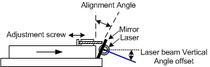
He fires a laser at a rotating drum with twelve mirror faces, each at a different adjustable vertical angle. The laser will hit a higher or lower point on the projection surface depending on which mirror it’s reflecting off – this creates resolution in the Y direction.
Timing the pulsing of the laser so that it reflects off the mirror at a certain horizontal angle provides the X resolution.
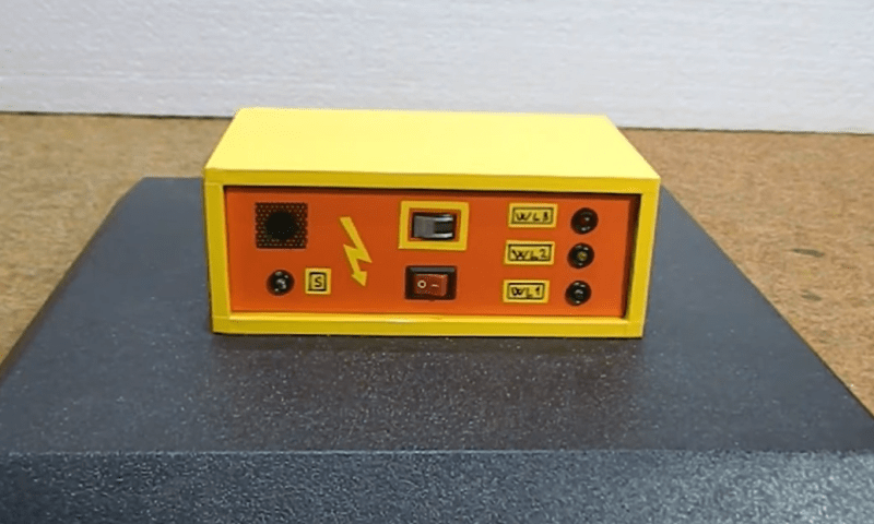
As you can already tell, speed and timing is critical for this to work. So much so that [Vitaliy] decided he wanted to overclock his Arduino – from 16 MHz to 24.576 MHz. Since this changes the baud rate, an AVR ISP II was used for programming after the modification, and the ‘duino’s hardware serial initialization had to be hacked too.
For the laser itself, [Vitaliy] designed some nifty driver circuitry, which can respond quickly to the required >50 kHz modulation, supply high current, and filter out voltage transients on the power supply (semiconductor lasers have no protection from current spikes).
On the motor side of things, closed loop control is essential. A photo-interrupter was added to the drum for exact speed detection, as well as a differentiator to clean up the signal. Oh, and did we mention the motor is from a floppy disk drive?
There’s something magical about a laser light show. Watching that intense beam of light flit back and forth to make shapes and patterns, some of them even animated, is pretty neat. It leaves those of us with a technical bent wondering just exactly how the beam is manipulated that fast.
Wonder no more as [Zenodilodon], a working concert laser tech with a deep junk bin, dives into the innards of closed-loop galvanometers, which lie at the heart of laser light shows. Galvos are closely related to moving-coil analog meters, which use the magnetic field of a coil to deflect a needle against spring force to measure current. Laser galvos, on the other hand, are optimized to move a lightweight mirror back and forth, by tiny amounts but very rapidly, to achieve the deflection needed to trace out shapes.
As [Zeno] explains in his teardown of some galvos that have seen better days, this means using a very low-mass permanent magnet armature surrounded by coils. The armature is connected to the mirror on one end, and a sensor on the other to provide positional feedback. We found this part fascinating; it hadn’t occurred to us that laser galvos would benefit from closed-loop control. And the fact that a tiny wiggling vane can modulate light from an IR LED enough to generate a control signal is pretty cool too.
The video below may be a bit long, but it’s an interesting glimpse into the day-to-day life of a lighting tech. It puts a little perspective on some of the laser projection projects we’ve seen, like this giant Asteroids game.
Thanks to [Alan Green] for the tip. He found it while researching his own laser galvo clock project, which you should definitely check out.
Playing Asteroids now isn’t quite what it used to be when it came out 40 years ago. At the time, the vector-scan display was part of the charm; making do with an emulator running on a traditional raster display just doesn’t quite do it for purists. But if you manage to build your own laser-projector version of the game like [Chris G] did, you’re getting close to capturing some of the original magic of the game.
There’s a lot to unpack about this project, and the video below does a good job explaining it. Where the original game used a beam of electrons flashing inside a CRT to trace out each object in the game, [Chris] substituted an off-the-shelf two-axis galvanometer from eBay and a 5-mW laser LED. This can project a gamefield on a wall up to two meters on a side, far bigger than any version of the machine ever built. The galvos are driven by op-amp drivers and an SPI DAC on a custom PCB. And in comparison to the discrete logic chips and 6502 running the original game, [Chris] opted for an ESP32.
As interesting as the hardware for this is, the real story is in the software. [Chris] does an excellent job running through his design, making the bulk of the video feel like a master class in game programming. His software is from scratch — no emulations here. As such it doesn’t perfectly reproduce the original games — no flying saucers and no spaceship explosion animations (yet) — but when coupled with the laser vector display, it certainly captures the feel of the original.
Being devoted Asteroids fans from back in the day, this one really pushes our buttons. We’ve seen laser-based recreations of the game before, but this one makes us think we can finally afford to recapture the glory of our misspent youth.
Lightning is a powerful and seemingly mysterious force of nature, capable of releasing huge amounts of energy over relatively short times and striking almost at random. Lightning obeys the laws of physics just like anything else, though, and with a little bit of technology some of its mysteries can be unraveled. For one, it only takes a small radio receiver to detect lightning strikes, and [mircemk] shows us exactly how to do that.
When lightning flashes, it also lights up an incredibly wide spectrum of radio spectrum as well. This build uses an AM radio built into a small integrated circuit to detect some of those radio waves. An Arduino Nano receives the signal from the TA7642 IC and lights up a series of LEDs as it detects strikes in closer and closer proximity to the detector. A white LED flashes when a strike is detected, and some analog circuitry supports an analog galvanometer which moves during lightning strikes as well.
While this project isn’t the first lightning detector we’ve ever seen, it does have significantly more sensitivity than most other homemade offerings. Something like this would be a helpful tool to have for lifeguards at a pool or for a work crew that is often outside, but we also think it’s pretty cool just to have around for its own sake, and three of them networked together would make triangulation of strikes possible too.
What does it take to make your own integrated circuits at home? It’s a question that relatively few intrepid hackers have tried to answer, and the answer is usually something along the lines of “a lot of second-hand equipment.” But it doesn’t all have to be cast-offs from a semiconductor fab, as [Zachary Tong] shows us with his homebrew direct laser lithography setup.
Most of us are familiar with masked photolithography thanks to the age-old process of making PCBs using photoresist — a copper-clad board is treated with a photopolymer, a mask containing the traces to be etched is applied, and the board is exposed to UV light, which selectively hardens the resist layer before etching. [Zach] explores a variation on that theme — maskless photolithography — as well as scaling it down considerably with this rig. An optical bench focuses and directs a UV laser into a galvanometer that was salvaged from an old laser printer. The galvo controls the position of the collimated laser beam very precisely before focusing it on a microscope that greatly narrows its field. The laser dances over the surface of a silicon wafer covered with photoresist, where it etches away the resist, making the silicon ready for etching and further processing.
Being made as it is from salvaged components, aluminum extrusion, and 3D-printed parts, [Zach]’s setup is far from optimal. But he was able to get some pretty impressive results, with features down to 7 microns. There’s plenty of room for optimization, of course, including better galvanometers and a less ad hoc optical setup, but we’re keen to see where this goes. [Zach] says one of his goals is homebrew microelectromechanical systems (MEMS), so we’re looking forward to that.
When it comes to trolling eBay for cool stuff, some people have all the luck. Whereas all we ever seem to come across is counterfeit chips and obviously broken gear listed as, “good condition, powers on”, [Les Wright] actually managed to get more than he bargained for with one of his recent eBay purchases.
In his video teardown and tour of an industrial marking laser, [Les] suggests that he was really just in it for the optics — which is not a surprise, given his interest in optics in general and lasers in particular. The 20-W CO2 laser once etched barcodes and the like into products on assembly lines, but with a 2009 date code of its own, it was a safe bet that it was pitched due to a burned-out laser tube. But there were still high-quality IR optics and a precision X-Y galvanometer assembly to be harvested, so [Les] pressed on.
The laser itself ended up being built around a Synrad RF-stimulated CO2 tube. By a happy accident, [Les] found that the laser actually still works, at least most of the time. There appears to be an intermittent problem with the RF driver, but the laser works long enough to release the magic smoke from anything combustible that gets in its way. The galvos work too — [Les] was able to drive them with a Teensy and a couple of open-source libraries.
Galvos, lenses worth more than $800, and a working laser tube — not a bad haul. We’ll be following along to see what [Les] makes of this booty.
Everyone should know by now that we love to follow up on projects when they make progress. It’s great to be able to celebrate accomplishments and see how a project has changed over time. But it’s especially great to highlight a project that not only progresses, but also gives back a little to the community.
That’s what we’re seeing with [Les Wright]’s continuing work with a second-hand laser engraver. It was only a few weeks ago that we featured his initial experiments with the eBay find, a powerful CO2 laser originally used for industrial marking applications. It originally looked like [Les] was going to have to settle for a nice teardown and harvesting a few parts, but the eleven-year-old tube and the marking head’s galvanometers actually turned out to be working just fine.
The current work, which is also featured in the video below, mainly concerns those galvos, specifically getting them working with G-code to turn the unit into a bit of an ad hoc laser engraver. Luckily, he stumbled upon the OPAL Open Galvo project on GitHub, which can turn G-code into the XY2-100 protocol used by his laser. While [Les] has nothing but praise for the software side of OPAL, he saw a hardware hole he could fill, and contributed his design for a PCB that hosts the Teensy the code runs on as well as the buffer and line driver needed to run the galvos and laser. The video shows the whole thing in use with simple designs on wood and acrylic, as well as interesting results on glass.
Of course, these were only tests — we’re sure [Les] would address the obvious safety concerns in a more complete engraver. But for now, we’ll just applaud the collaboration shown here and wait for more updates.


 I suppose I can take credit for introducing the super awesome [Fran Blanche] to Hackaday’s very own crotchety old man and Commodore refugee [Bil Herd]. I therefore take complete responsibility for


 This novel characteristic has found applications in a number of areas. In particularly the finishing of precise mirrors and lens used in semiconductor and astronomical applications. This method uses an electromagnet to change the viscosity of the slurry used to polish mirrors, removing imperfections. The Hubble telescope’s highly accurate mirrors were apparently finished using this technique (though hopefully not